Basic Terminology
The following definitions are useful to help you understand the examples and commands in this guide. For more detailed information search or browse the online help (Help →Online Help).
Cells and Regions in a System
A system normally consists of one cell. This cell contains one or several regions in which the diffusion problem is to be solved. A system of diffusion equations is solved for each region. The size of the system is the sum of sizes of all the regions in all the system’s cells.
The interface between two regions typically moves as the result of a simulation, that is, the regions grow or shrink. Such an interface is called an inner interface. The boundary of a cell is called an outer interface and the condition of this type of interface may be affected by the choice of boundary conditions.
For some simulations it is useful to have several cells in a system. Matter can move between cells. However, it is assumed that there is diffusional equilibrium between all cells (this means that there are no differences in diffusion potentials between cells). In other words, the size of a cell is fixed during the simulation.
By default this is a closed system, which means that matter cannot move across its boundaries. However, you can change this setting for both the lower boundary (left side/centre) and the upper boundary (right side/surface) of the system. You can also set these boundary conditions to vary as a function of time, temperature and/or pressure.
Regions and Grids
A region contains one or more phases. If a region contains several phases one of those must be entered as a matrix phase whereas the others are entered as spheroid.
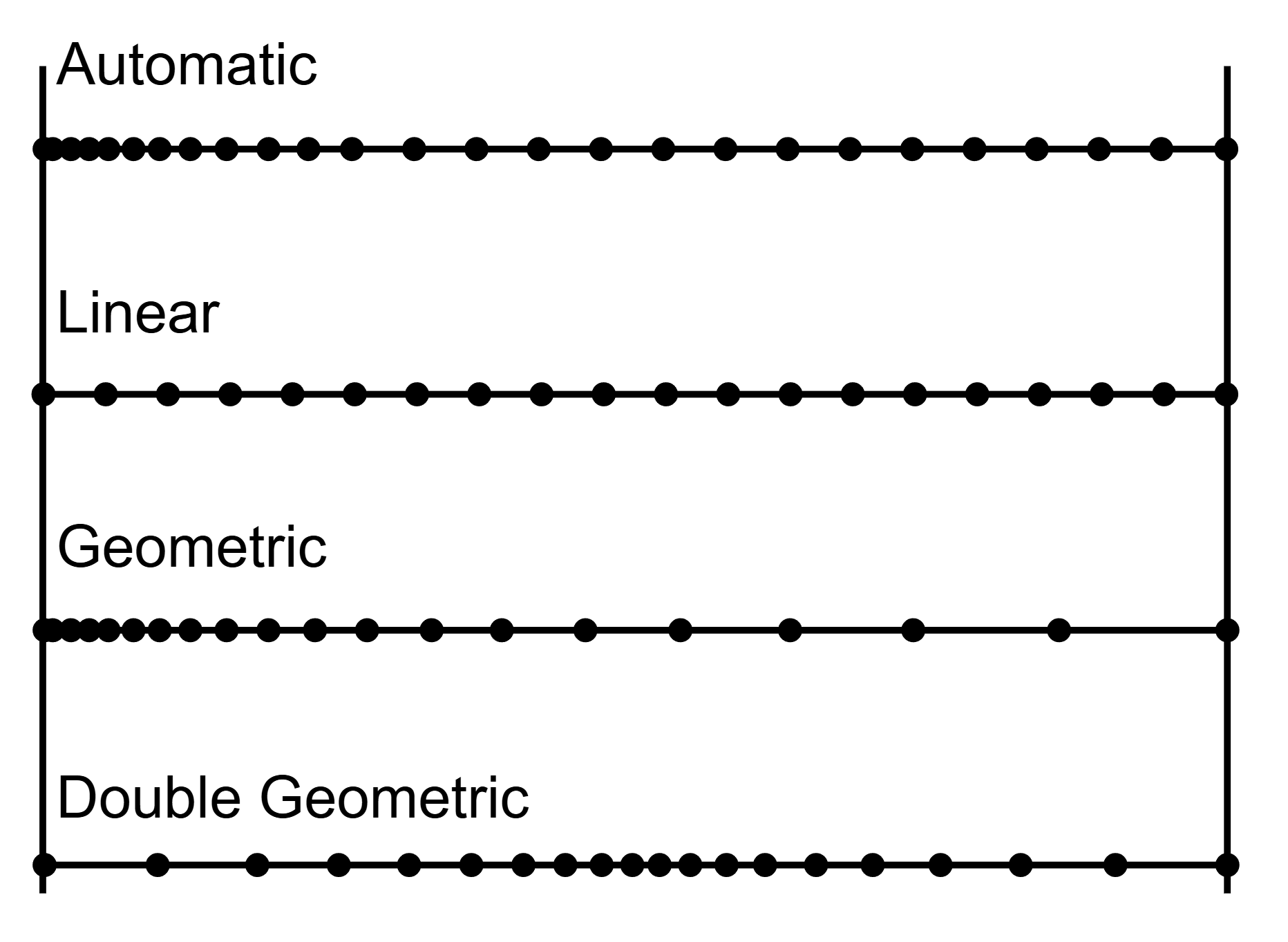
A region must also contain a number of grid points. The composition is only known at these grid points and the software assumes that the composition varies linearly between them. The amount and composition of all the phases present at a single grid point in a certain region are those given by thermodynamic equilibrium keeping the over-all composition at the grid point fixed.
These grid types are used in diffusion simulations: automatic, linear, geometric, and double geometric. When you are setting up the simulation, in either Console Mode or Graphical Mode, a region must have a grid defined.
Phases
Each region contains one or more phases. A phase can be of the matrix, spheroid or lamellar type. A phase can be introduced with the status active (the default) or inactive.
An inactive phase is a phase which does not participate in the calculations until it is stable. If a phase is inactive, then the driving force for precipitation of the phase is continuously monitored. When the driving force exceeds a predefined positive value, the phase take parts in the simulation and the phase automatically becomes active. A new region is then created and the formerly inactive phase is entered as the matrix phase of the new region. The name of the region is set to the name of the phase that just became active but with R_ added as a prefix.
Composition
This section or topic is specific to Console Mode.
For Graphical Mode, see Diffusion Module Terminology in Graphical Mode.
Two types of composition variables are used within the program: site-fractions and u-fractions, although you can also use weight fraction or mole fraction, for example.
The site-fractions are used to set up the problem and interface with POLY-3 (in Console Mode).
The u-fractions are used in the diffusion equations.

The summation is only performed over the substitutional elements. The choice of the volume fixed frame of reference in the calculations make it convenient to use a composition variable which is related to the volume. The definition of the u-fraction is based upon the assumption that a species may or may not contribute to the volume of a phase. An interstitial element is assumed to not contribute to the volume. Substitutional elements are assumed to contribute equally to volume.
Geometry and Coordinates
The Diffusion Module (DICTRA) can only handle diffusion problems where composition vary along one spatial coordinate. The geometry of your system can be planar, cylindrical or spherical.
Planar Geometry
This geometry corresponds to an infinitely wide plate of a certain thickness. If the system has a planar geometry then the lower boundary (the zero coordinate) is at the left side of the system. The upper boundary (the coordinate with the highest value) is at the right side of the system.
Cylindrical and Spherical Geometries
- Cylindrical geometry corresponds to an infinitely long cylinder of a certain radius.
- Sypherical geometry corresponds to a sphere with a certain radius.
By default for both geometries, the lower boundary (the zero coordinate) is at the centre of the cylinder/sphere. The upper boundary (the coordinate with the highest value) is at the surface of the cylinder/sphere. You can enter a left most coordinate that is larger than zero to allow for tube and hollow sphere geometries.
Boundary Conditions
Boundary conditions are conditions that define how matter behaves at the boundaries of your system. By default, matter is not allowed to cross the system boundaries.
You can change the setting for both the lower boundary (left side/centre) and the upper boundary (right side/surface) of the system.
