Working with the Process Metallurgy Module
Working with the Process Metallurgy Calculator allows you to easily define complex metallurgical reactions. The calculator streamlines how you set up these steel and slag systems but there are details about various inputs and outputs that are different from other calculators. This topic is a general collection of information related to the Process Metallurgy Module and is intended to help you better understand how to interpret and make choices when you are setting up your steelmaking simulation.
It is not possible to use custom user databases with the Process Metallurgy Module. This is because several internal calculations, such as determining the component compositions of ionic phases, are dependent on the database. Therefore, only TCS Metal Oxide Solutions Database (TCOX) versions 8 and newer, and to a limited extent, OXDEMO, can be used with this Module.
For information about saving and deleting materials used with the Process Metallurgy Calculator, see Working with the Material Manager. Also see the next section.
For more details about these fields, see Defining the Equilibrium Simulation. For information about saving and deleting materials, see Working with the Material Manager.
There are three groups to define: Steel (or another user-defined Metal group), Slag, and Gas.
It is recommended you open the PMET_01: Basic Oxygen Furnace (BOF) example to follow along with the descriptions. Version b is used in the screenshots.
Open the example project file(s) from Thermo‑Calc Help → Example Files → Process Metallurgy → PMET_01_Basic_Oxygen_Furnace.tcu. Choose a, b, or c versions of the example based on whether you have a license for the TCOX database.
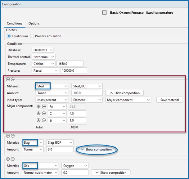
In the image below, the red-highlighted area is where the Steel material group is defined. The drop-down menu that displays Steel_BOF shows a user-defined material. This can be defined and then saved to the material library.
The three material group areas on the Process Metallurgy Calculator where you can define components and save materials. You can create your own material groups using the Material Manager.
When you click Show composition next to any material group, additional fields display to give composition and input type where you can further define each material group. You can remove materials and add and remove material groups using the Material Manager (available on the Configuration window → Options tab).
In the example, click Show composition next to the Slag and Gas groups to see how the Slag_BOF and Oxygen materials are defined.
From this composition area you can click the Save material button to add the new material to the group's list. The newly named material composition is then available for use with that material group. In this example, the Steel_BOF material was defined first and then named at the end. It is now available in the lists wherever you select the Steel material or need to choose quantities to plot.
After defining and saving a material composition, the named material is available for selection in a variety of places such as when choosing quantities on the calculator and defining axis variables on the Plot Renderer.
To add one or more material groups click the add  button. Click the minus
  button to remove a material group. The new material inherits the default settings of that group.
When you choose a One Axis or Grid Calculation Type, you also choose a Quantity under the Grid Definitions. The relationship between these quantities and how the material group composition is defined as follows.
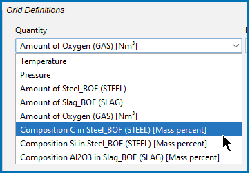
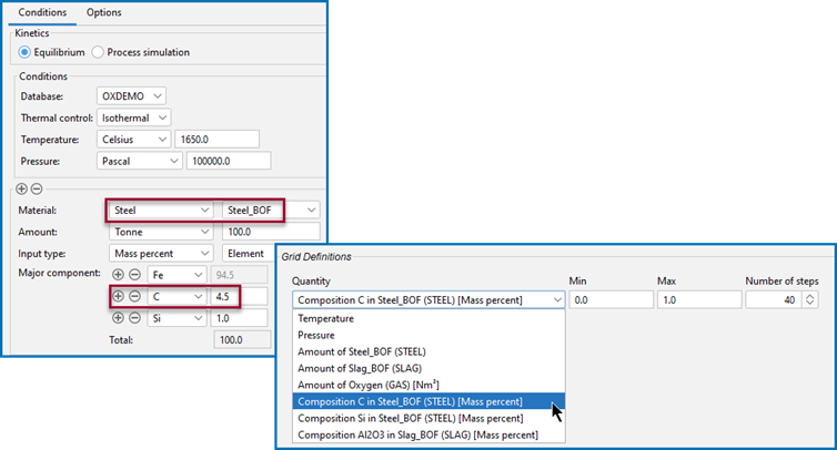
The following uses Composition of C in Steel_LF (STEEL) as an example quantity for a One Axis calculation.
Under Grid Definitions, the availability of the Quantity in the list is based on the material (Steel_BOF) that is defined and saved for the Steel group (or any user-defined metal, slag, or gas group).
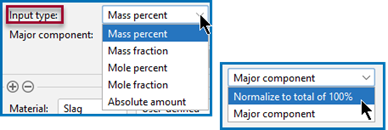
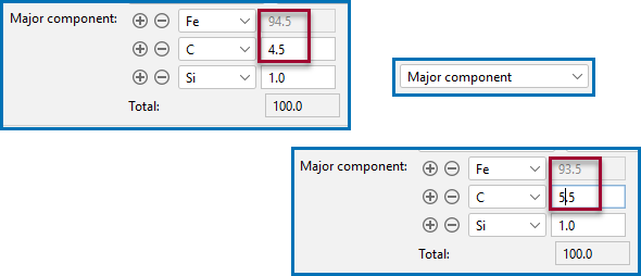
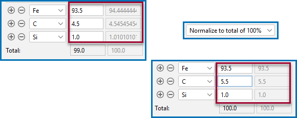
Click Show composition so that when you choose the Input type for a steel the composition of the elements can be set up using a combination of settings starting with Mass- or Mole percent, Mass- or Mole fraction, or for Equilibrium calculations, Absolute amount. Then you further choose to define the composition using either the Major component or Normalize to total of 100% options.
The Amount of X in Y quantities you can choose from the various drop-down lists (such as under Grid Definitions) are defined as Min-Max variation of the component X in Y. If a dependent element is present that is adapted as usual.
When you use Major component, as you add other components or adjust the composition, the major one is adjusted to be the rest of the composition.
When you use Normalize to total of 100%, the sum is adapted to 100%. This is useful if you need to work with a given composition that does not sum up to 100%.
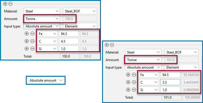
Sometimes its preferable to use input of amount of each component Amount by weight (Tonne, Kilogram, Gram, or Pound), it can useful to choose Absolute amount as the Input type. In this case, the total amount of material automatically adjusts the total.
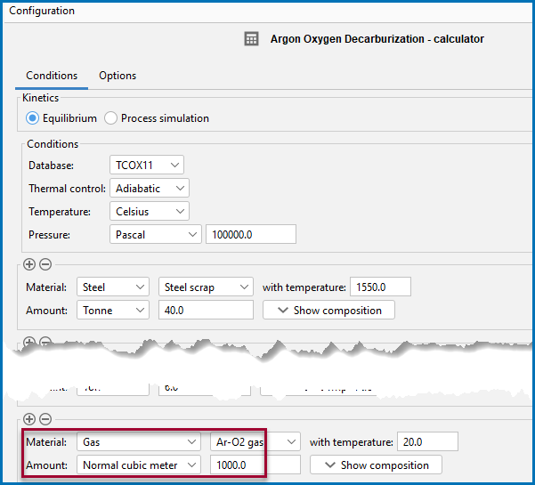
For the Gas component, if you choose Normal cubic meter as the Amount, then beside regular mass units, the amount of gas can also be provided in Nm3.
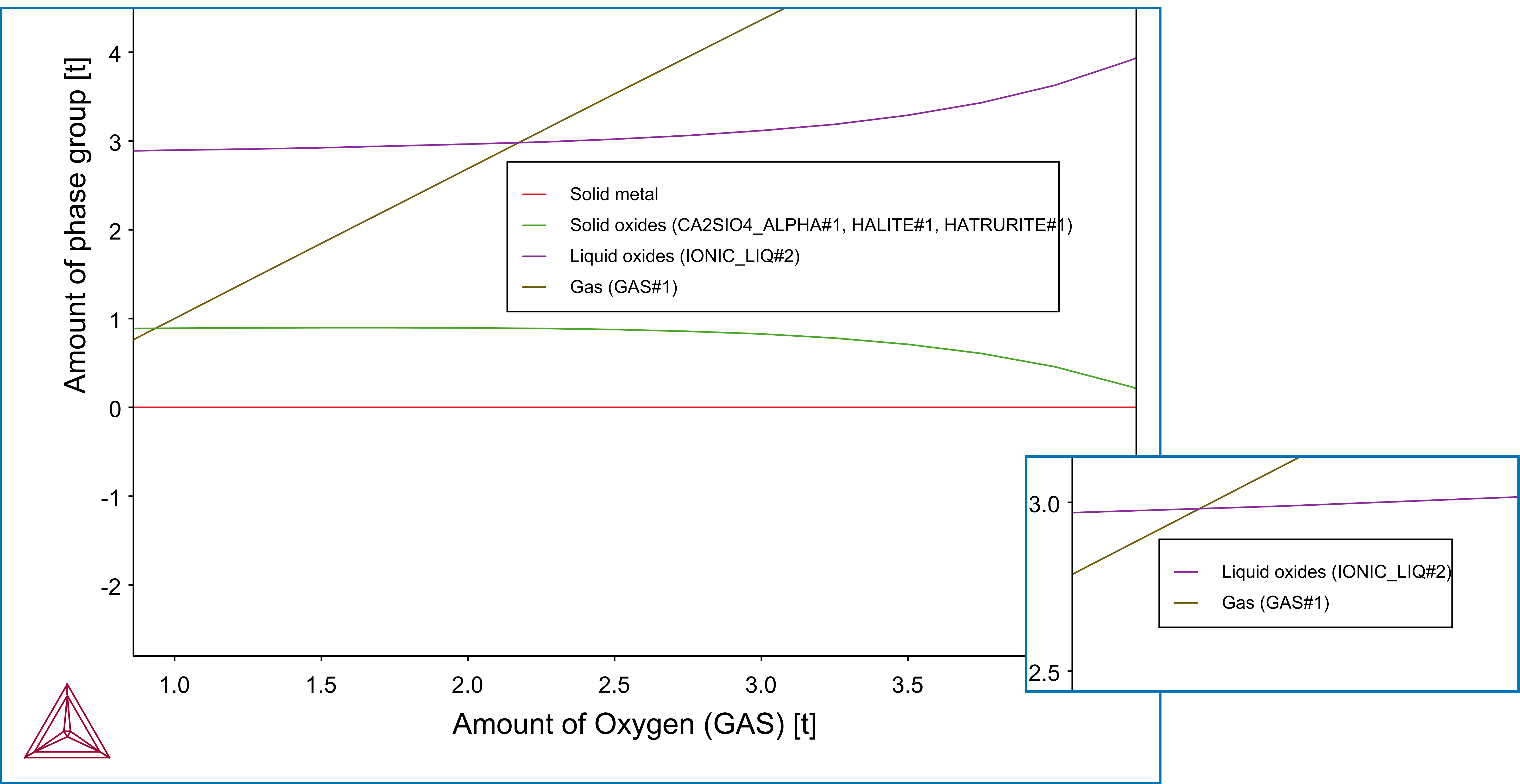
The phases that are plotted after you run a simulation are grouped together on the plot to make the interpretation of the results easier.
Phases of similar type are bundled together in the groups liquid metal, solid metal, solid oxides, liquid oxides, and gas. Except for the gas phase, all the groups can have more than one phase. This grouping is particularly useful for liquid metal and liquid oxide because they are both described by the same phase, IONIQ_LIQUID, and because there is typically two or more compositions sets of IONIQ_LIQUID. This is also useful for solid oxides, because a large number of phases can be stable, making the interpretation of results difficult without this grouping.
The term oxides in the Process Metallurgy Module can also mean carbides, sulfides, and fluorides.
The slag properties describe the capability of a slag to take up sulfur from the metal melt. The Process Metallurgy Module defines so-called phase groups. These contain all phases of a certain kind, for example all solid slag or all slag phases. The component composition of such a phase group is calculated by weighting the component composition of each phase with their fraction in the group.
This allows to calculate slag properties for the phase groups, for example for the overall slag.
On the Plot Renderer (for axis quantities) and Table Renderer there is an option to choose or define the Slag property. The associated quantity that you select has these options: All, B2, B3, B4, Bas2, Bells ratio, Ls, or Log10 (Sulphur capacity).
Details, including references and equations, are described in Process Metallurgy Slag Properties.
When setting up the Process Metallurgy Calculator under the Equilibrium Kinetics branch, you choose the thermal control to be either Isothermal or Adiabatic. Adiabatic calculations assume no heat and mass exchange with the environment during the equilibrium reaction. The adiabatic process is implemented by an isenthalpic process with constant pressure (i.e. H=const), which is equivalent.
Beside regular mass units, the amount of gas can also be provided in Normal cubic meter (Nm3). The applied reference conditions are 1013.25 hPa and 15.0 °C (according to ISO 2533).
There are slightly deviating definitions present in the industry, which need to be converted for precise results. For most applications of the Process Metallurgy Module this difference has a minor influence.
The composition of all ionic phases is provided as elemental as well as component composition (i.e. Fe2O3, FeO, CaO, …). In order to provide a representation similar to that usually used in the industry, the content of S is provided as elemental content and the content of P is given as component content of P2O5. This is a simplification because P and S can also be present as sulphates and phosphates in the slag and can bind to different metal cations. This can cause deviations in the overall component composition if the content of S and P is high in the phases. In doubt, the elemental composition can be used, it will always be exactly correct.
For non-ionic phases such as ALABANDITE, always the elemental composition will be shown only. This is also true if the IONIC_LIQ composition cannot be described by components only due to constraints of the overall composition (for example if the material has been oxidized completely and forces a certain composition of the ionic liquid slag).
The oxygen partial pressure in the gas phase is calculated with the following formula:

In the formula, p describes the total system pressure and AC the activity of oxygen in the gas phase.
The chemical activity of each component AC(COMPONENT, REFERENCE_PHASE) is available either with reference to the liquid or the solid slag phase. It can only be calculated for components being present in the thermodynamic database.
When you are working with the Process simulation branch you set up a process schedule. There are some useful details about this described in Working with the Process Schedule.
The nature of a Process simulation requires a dynamic choice of the time step lengths. To understand this better, see About Dynamic Time Stepping. These settings are done on the Process Metallurgy Calculator: Options Tab.
It is possible to apply variable pressure during process metallurgical calculations, which is relevant in various processes such as Vacuum Oxygen Decarburization (VOD) or Ruhrstahl-Heraeus (RH). See About Pressure-Dependent Calculations.
