Setting Up a Process Metallurgy Simulation
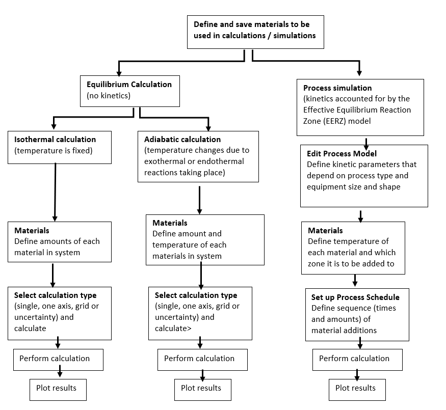
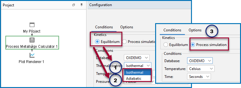
The following basic steps need to be carried out to set up calculations in the Process Metallurgy Calculator. There are three branches of simulation to choose from on the Configuration window when setting up the simulation an isothermal equilibrium calculation, an adiabatic equilibrium calculation, and a process simulation.
Examples of using the Process Metallurgy Calculator for Basic Oxygen Furnace (BOF) (with and without kinetics), a Ladle Furnace (LF) simulation, an Argon Oxygen Decarbarization (AOD), and a Vacuum Oxygen Decarborization (VOD) simulation are included with your installation.
You can find several learning resources on the Process Metallurgy page of our website (or in Thermo‑Calc, go to Help → Thermo‑Calc website). You can also subscribe to the Thermo‑Calc newsletter to be kept up-to-date about upcoming releases, training, examples, videos and much more.

The three branches of simulations available for the Process Metallurgy Calculator (1) an isothermal equilibrium calculation, (2) an adiabatic equilibrium calculation, and (3) a process simulation.
Equilibrium Simulations
Two Equilibrium simulation types are available: Isothermal and Adiabatic. In general for the equilibrium simulation, the three most common material groups—Steel, Slag, and Gas—are automatically included with the default composition input types that are relevant to each material group. You can add materials and save your material compositions directly from the Process Metallurgy Calculator and quickly access these for other simulations. For example, you might want to predefine compositions of steels, ferro-alloys, slags, and slag additions. The overall composition of the steel and slag is then obtained by adding amounts of these predefined materials.
Each group of materials is automatically added to the similar group where it is defined. You can manage these groups using the Material Manager (see Working with the Material Manager).
For adiabatic calculations, the selection of material type (steel, slag, gas) has an influence on the calculation. For isothermal calculations, the results are identical.
The reason the selection of materials for adiabatic calculations has an influence is because there are different strategies to calculate the enthalpy of the materials at the temperature at which these are added. Therefore, defining FeO as a steel containing 50 at% Fe and 50 at% O or as a slag with 50 at% Fe and 50 at% O or as slag with 100% FeO, all result in different enthalpies assigned to the component FeO, which in turn results in different equilibrium temperatures.
Defining the Equilibrium Simulation and Equilibrium Simulation: Conditions Tab
Adiabatic Calculations: Material Enthalpy
Process Simulations
When you choose to do a Process simulation it includes the reaction kinetics. Using the EERZ (Effective Equilibrium Reaction Zone) model, you can first define your materials as you do with an Equilibrium simulation. You also need to define the Process model where you define the kinetic parameters of the simulation by setting up reaction zones, reaction rates, heat transfer coefficients, and so forth. You also need to define the Process schedule where the sequence and amounts of added materials are defined.
Defining the Process Simulation and Process Simulation: Conditions Tab
Calculation Types
The calculations available for an Equilibrium simulation, for both isothermic and adiabatic calculations, are Single equilibrium, One Axis, Grid, and Uncertainty. After adding a Plot Renderer or Table Renderer, you can choose a variety of quantities, including slag properties such as Bells ratio and B2, to output results that provide useful visual representations of the steelmaking systems being analyzed.
Process Metallurgy Calculator and Defining the Equilibrium Simulation
