Additive Manufacturing Module Theory
This section is an overview of the underlying fundamental theory used and applied to the calculations when you are setting up the AM Calculator using one of the Additive Manufacturing Simulation Types.
The settings related to the following are defined for the AM Calculator starting with the AM Calculator Conditions Settings section.
Energy Equation: The Enthalpy Formulation
The following formulation is based on a simple assumption that each volume element, which may contain several dendrites or a considerable part of a dendrite, is approximated as homogeneous, i.e., it is sufficient to characterize the whole volume with a single set of state variables. This assumption thus excludes the direct account of varying composition caused by microsegregation within the element.
The enthalpy formulation is based on the conservation of energy and is essentially equivalent with Fourier’s second law:
 is the enthalpy density and
  is its time derivative.
The enthalpy density is related to the molar enthalpy  and molar volume
  by:
by:
[Eq. 2]

 denotes the divergence operator and
  is the heat flux given by Fourier’s law:
[Eq. 3]

where  is the heat conductivity,
  denotes the gradient operator and
  is the temperature.
  is a source term and represents the heat added from the outside at a certain point. In modeling of a process like welding or additive manufacturing this is a key term and requires a lot of modeling.
As state functions the enthalpy and the molar volume depend on temperature, state of phase, and composition of the individual phases. In a volume element approximated as homogeneous, one thus has:
[Eq. 4]

where  is the mole fraction of the phase
  and
and  is the mole fraction of
  in
in  . The time derivatives thus are:
Here  is the molar heat capacity of the
  phase and
  its volumetric thermal expansion. For a given volume element the rates can be calculated from Thermo‑Calc for the temperature, fraction of phases and their composition with the input of the rates
  and
and  .
.
The rate of change of the enthalpy density, i.e., the left-hand side of Eq. 1 thus is obtained as:
[Eq. 8]

The first term inside the brackets represents the change for a constant number of atoms due to a change in temperature or phase. The second term represents a change in volume for a constant number of atoms. However, the second term is balanced by a corresponding contribution in the heat flux, which we do not usually account for, and we should thus leave it out.
The fraction of phases sums up to unity and in the case of only one solid phase:

In most treatments the positive quantity

treated as constant and referred to as the latent heat. It is also common to neglect the difference in heat capacity between solid and liquid and the variation of  with composition. Eq. 6 then is simplified into
[Eq. 10]

By the same token

is often approximated as constant and so Eq. 7 is simplified into
[Eq. 11]

where  is given by Eq. 5 and yields

Eq. 9 now becomes:
[Eq. 12]

and Eq. 1 becomes:
The Equivalent Heat Capacity Method Using Thermo‑Calc
If it is further assumed that the fraction liquid  is a unique function of temperature one has:
[Eq. 14]

and Eq. 13 may be further simplified to:
where the effective heat capacity  is given by:
[Eq. 16]

Eq. 15 is a normal heat-flow equation and the complication of the liquid/solid phase transformation is taken into account by means of an effective heat capacity. This method is referred to as the equivalent heat-capacity method by Rappaz [1989Rap].
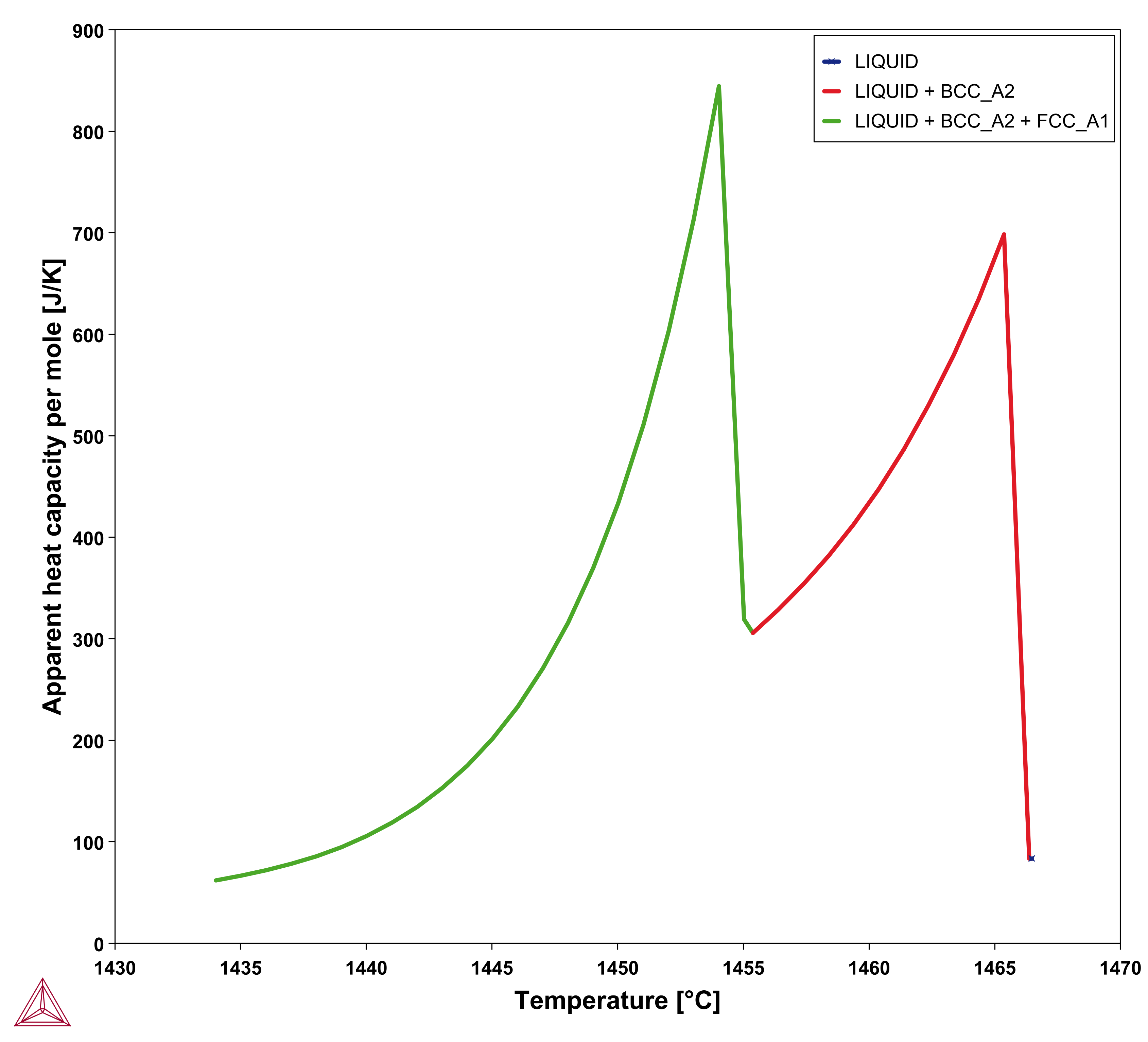
It then remains to be discussed how to determine  . It must be given by some extra information. Traditionally it was taken from experimental information but more recently it has been taken from the Scheil equation. The original equation was based on a number of approximations which are unnecessary today when thermodynamic and properties databases and efficient software such as Thermo‑Calc are available. In fact, when using Scheil in Thermo‑Calc one can directly calculate
  , referred to as apparent heat capacity, for a given initial composition of the liquid. A possible approach thus is to calculate
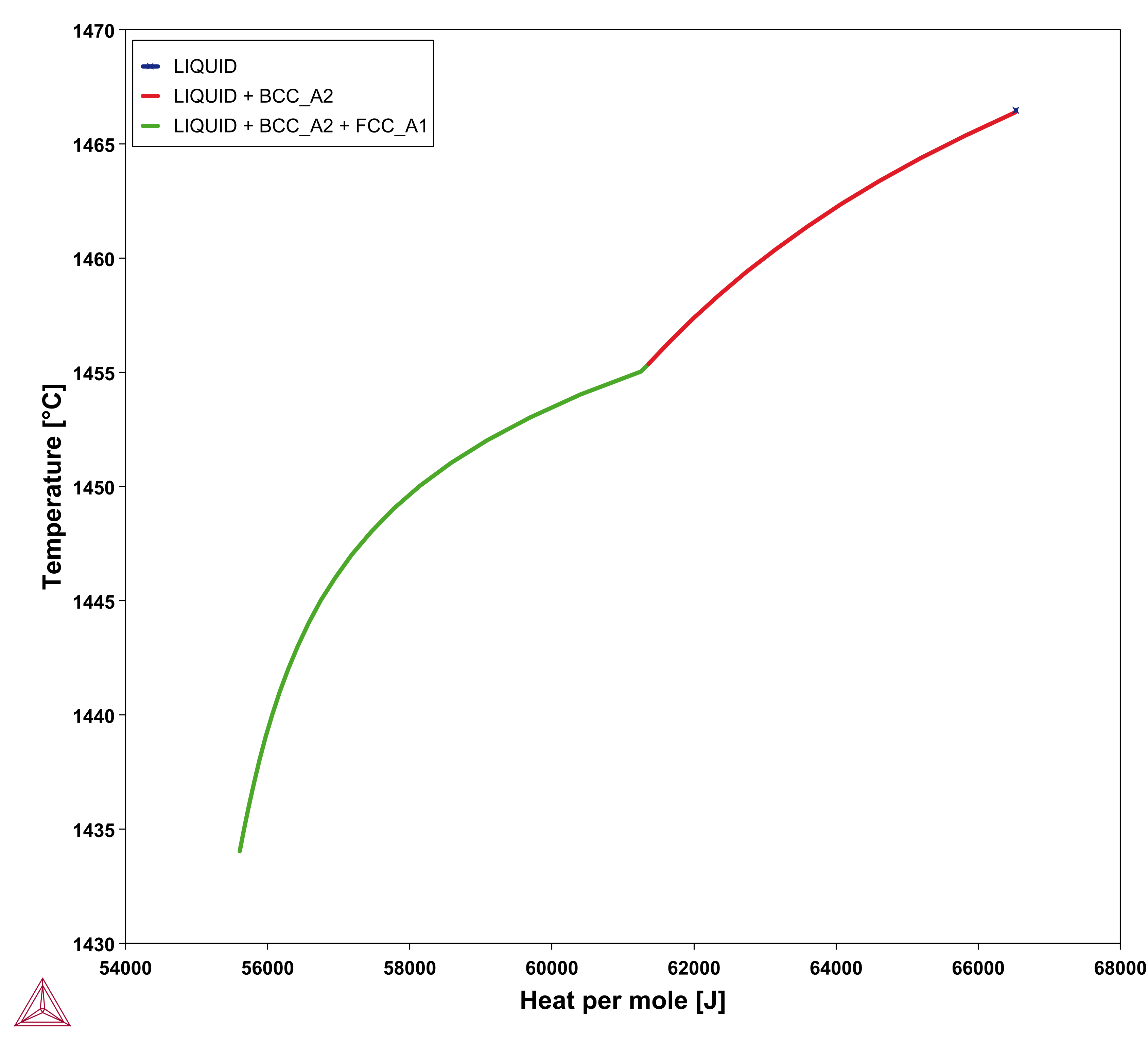
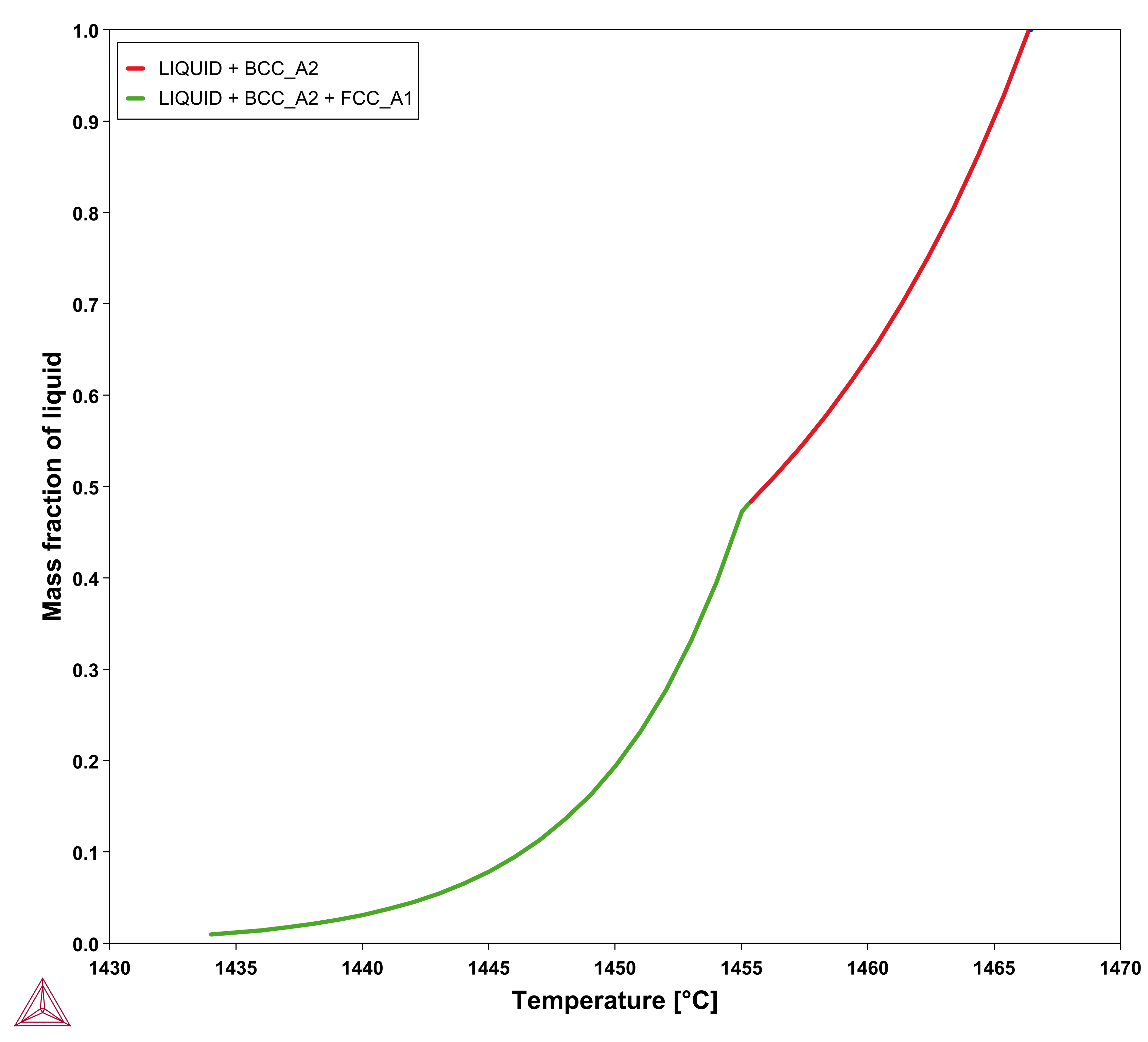
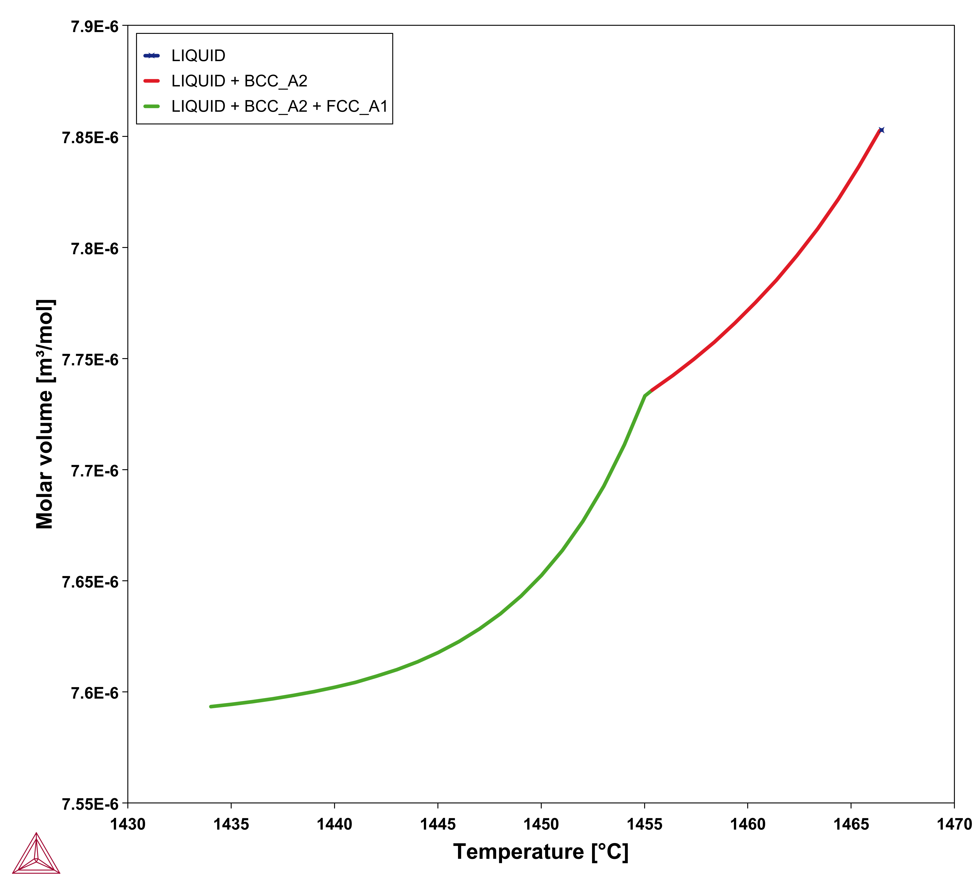
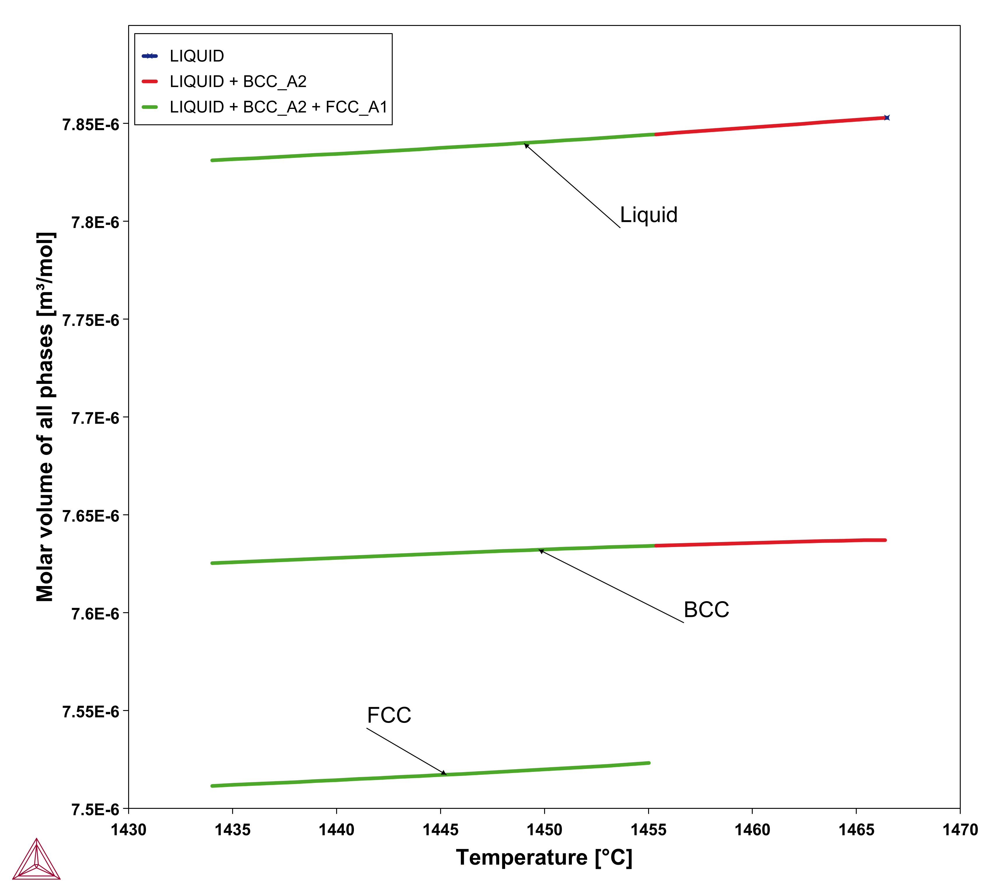
  for the alloy under consideration and then store the result as a table and use that in the solution of Eq. 15. The molar volume may be extracted from the same calculation. An example for a 316L type of stainless steel is shown in the plots below.
|
|
Figure 1: Results of a Scheil simulation of Fe-18Cr-10Ni alloy showing the mass fraction of the liquid (left) and the apparent heat capacity (right) both as a function of temperature.
|
|
Figure 2: Molar volume from a Scheil simulation of Fe-18Cr-10Ni alloy. The right plot shows all phases as a function of temperature.
The Enthalpy Method Using Thermo‑Calc
In the enthalpy method we keep Eq. 1 and use Eq. 9 to write
As pointed out by Rappaz [1989Rap] there is no mathematical difference between the enthalpy method and the equivalent heat capacity method because the former is simply the integral of the heat capacity over  . For numerical reasons the cusps in the heat capacity may be disadvantageous and the enthalpy has a nicer behavior as shown in the plot below, where it gives temperature as a unique function of enthalpy.
In the Additive Manufacturing Module, we therefore use Eq. 17 to predict the evolution of temperature during the laser powder bed fusion (LPBF) process for the given material properties and process parameters.
Steady-state Formulation
An important approximation is when one can solve the stationary heat-flow equation for a volume element moving with the heating source. In that case, we neglect the left-hand side of Eq. 17 and add a translation term as follows:
[Eq. 18]

Where  is the velocity of the heat source. In case of additive manufacturing,
  is the scanning speed.
Fluid Flow
When there is also fluid flow involved, a fluid transport term has to be added to the heat-flow equation and one obtains:
[Eq. 19]

where  is the velocity vector field and may be imposed or obtained from the solution of the Navier-Stokes equation:
[Eq. 20]

where  is the density related to the molar volume by means of
[Eq. 21]

 is the molar weight in kg mol-1.
  is the viscosity,
  is a volume force, e.g., gravitational forces, and
  is the internal pressure. The equation is often combined with approximating the liquid as incompressible.
[Eq. 22]

Large Eddy Simulation Used for Fluid Flow
The use of a subgrid model [1963Sma] relies on the eddy-viscosity assumption and this is applied to account for the unresolved turbulent motions that cannot be directly simulated due to computational limitations. The Smagorinsky model is the default for fluid flow, and it provides a simple way to estimate Subgrid-scale (SGS) viscosity in large eddy simulation as,

where:
-
 is the Smagorinsky constant (default value is 0.18).
 -
 represents the filter width (length scale).
 -
 is the magnitude of the resolved strain rate tensor.
Heat Source Models
See additional theory related to heat sources in About the Heat Source Models and About Heat Source Calibration. Settings information specific to heat sources is also found in AM Calculator Heat Source Settings.
Numerical Boundary Conditions
In order to obtain temperature distribution during the LPBF process in the Additive Manufacturing (AM) Module, incorporating fluid flow inside the melt pool, we couple energy equations with the Navier-Stokes equations, as explained earlier. In order to accurately reflect the physical process, both of these equations are subjected to a certain set of boundary conditions, which are given as follows.
Boundary Conditions for Energy Equation
The energy equation is subjected to four different boundary conditions. The first boundary condition is defined on the top surface (either the powder bed surface or the solid substrate) and represents the energy lost due to convection and radiation to the surrounding gas.
[Eq. 23]

where  is the convective heat transfer coefficient,
  is the surface radiation emissivity and

is the Stefan-Boltzmann constant.  is the ambient temperature or the temperature of the surrounding gas in the build chamber and can be set in the AM Calculator configuration.
The second boundary condition represents the heat lost through the vertical walls of the domain and for simplicity we have chosen adiabatic boundary conditions for these surfaces. The boundary condition for the vertical walls of the computational domain is thus given as:
[Eq. 24]

The third boundary condition reflects the temperature of the base plate and is therefore applied to the bottom of the computational domain. Here we have assumed that the base plate of the build part is kept at a constant temperature and the boundary condition is therefore given as:
[Eq. 25]

 is the base plate temperature and can be set in the AM Calculator configuration.
The fourth and the most important boundary condition is the evaporation boundary condition that represents the heat lost due to evaporation of the material. Evaporation is implemented using a physics-based approach where the heat loss due to evaporation ( ) is given as:
[Eq. 26]

where  is the evaporation flux and
  is the evaporation enthalpy. For a multicomponent system, the evaporation flux is given as follows:
[Eq. 27]

where  is the driving force for evaporation,
  is the molar mass of the gas,
  is the gas pressure inside the chamber,
  is the atmospheric pressure, and
  is the universal gas constant. The driving force for evaporation, the evaporation flux, and the molar mass of the gas are all temperature-dependent material properties which are obtained from Thermo‑Calc databases and are included in the material library whereas the gas pressure inside the chamber can be set from the AM Calculator configuration.
Boundary Conditions for Navier-Stokes Equations
For the velocity, a no-slip boundary condition is used for the bottom surface of the computational domain. A no-slip boundary assumes that at a solid boundary, the fluid will have zero velocity relative to the boundary. For the pressure, a pinned boundary condition is used.
For the melted liquid at the top, the symmetry (front - in a steady-state simulation), and the keyhole surfaces, the free-slip boundary is used.
The most important boundary condition in Navier-Stokes setup is the Marangoni boundary condition that reflects the tangential force on the surface of the melt pool due to temperature variation of surface tension or the so-called Marangoni effect. In AM, large temperature gradients on the surface of the melt pool, leads to the Marangoni effect and is the primary cause of convective flow inside the melt pool. The Marangoni shear stress ( ) is modeled using the following equation:
[Eq. 28]

where  is the surface tension and
  represents the tangential component of the spatial derivative.
Surface tension is also a temperature-dependent material property which is obtained from Thermo‑Calc databases and is included in the material library.
Thermophysical Properties of Powder Material
When the option “Use separate material properties for powder” is selected, a different thermal conductivity, density and molar volume is used for the powder material as compared to the solid substrate. The above mentioned properties depend on the porosity ( ) of the powder. The density (
 ) and molar volume (
 ) of the powder are then simply given as follows:


For thermal conductivity of powder  , an empirical expression is used which was suggested by Xue and Barlow [1991Xue]. The thermal conductivity of powder thus also depends on the conductivity of the surrounding gas. For simplicity, the surrounding gas is assumed to be air. The thermal conductivity of powder is given as follows:
[Eq. 29]

where  .
.
References
[1963Sma] J. Smagorinsky, General circulation experiments with the primitive equations: I. The basic experiment. Mon. Weather Rev. 91, 99–164 (1963).
[1989Rap] M. Rappaz, Modelling of microstructure formation in solidification processes. Int. Mater. Rev. 34, 93–124 (1989).
[1991Xue] S. Xue, J.W. Barlow, Models for the prediction of the thermal conductivities of powders, Solid Freeform Fabrication Symposium Proceedings, Center for Materials Science, University of Texas at Austin, Austin, TX (1991), pp. 62-69.


