Diffusion Calculator Settings (Single Phase)
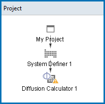
After you have completed the settings for the System Definer you start defining the diffusion parameters on the Diffusion Calculator.
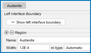
In any simulation at least one region must be defined. This is a named container that designates a certain part of the domain. In this case it is the whole domain. The name of a region is arbitrary and specified by you.
The use of regions becomes clearer in the context of moving phase boundary simulations.
A region must contain a numerical grid specified by width and type. In this example, a 10-4 m (1e-4 m) wide, linear (i.e. equidistant) grid is used with 50 grid points.
Define the Region and Composition Profiles
-
In the Project window, right click the System Definer node and select Create New Successor → Diffusion Calculator. A Diffusion Calculator node is added to the tree structure.
If you used the Diffusion template, then this activity node is already there. Click the Diffusion Calculator node to access the Configuration window settings.
- You are now going to add the settings to the Configuration window on the Conditions tab. Keep the defaults for Composition unit (Mass percent) and Length unit (Meter). A Planar Geometry is used for all the examples.
- In the Region Name field, enter
Austenite. This name is automatically updated on the tab. - In the Width field replace the default with
1e-4. Keep the defaults for number of points (50) and type of grid (Automatic). - From the Phase list, select FCC_A1.
In the Visualizations window, the Composition Profile tab displays a preview. The initial composition profile must be specified for all regions. Since there are only two elements, Fe and Ni, the initial composition profile must only be given for one of them.
- Next to Composition profiles the default selected is Given by function. Choose Fe as the Dependent component.
There are many ways to specify the composition profile, e.g. an arbitrary position dependent function. In this example, the default Linear type is used. The initial profile for Ni is a Linear variation. In the from field enter
10and in the to field enter50. These settings mean that the profile goes from 10 (mass-%) on the lower/left hand side of the system to 50 (mass-%) on the upper/right hand side of the system.Watch as the Composition Profile changes on the Visualizations window to match these values.
Define the Thermal Profile
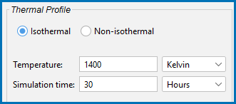
The default Isothermal profile is used for this example. A constant temperature of 1400 K is used during the simulation, which is run for 30 hours. Enter these values in the fields:
- In the Temperature field, enter
1400. Keep Kelvin as the default unit. - In the Simulation time field, enter
30. Select Hours from the list.Watch as the Thermal Profile tab on the Visualizations window updates to match these values.
There are no changes to the default settings on the Options tab. You can click the tab to see what settings are available and then search the Online Help (press F1) for more information.


