Equilibrium Simulation: Conditions Tab
The following outlines what you can set on the Configuration window Conditions tab when working with the Process Metallurgy Calculator and an Equilibrium simulation.
Also see Defining the Equilibrium Simulation for instructions that walk you through the steps that represent a simplified steelmaking process. A more complex process is described in Defining the Process Simulation.
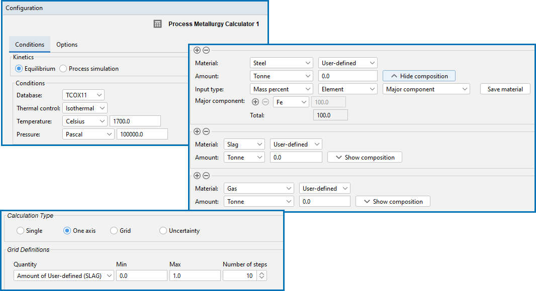
An example of the different settings areas for a default Configuration window for a Process Metallurgy Calculator when an Equilibrium simulation type is selected. There are many settings available depending on the parameters.
The most recent available version of TCS Metal Oxide Solutions Database (TCOX) is selected by default.
The Process Metallurgy Module requires both a valid Maintenance and Support Subscription (M&SS) and a license for the TCS Metal Oxide Solutions Database (TCOX8 or newer).
It is not possible to use custom user databases with the Process Metallurgy Module. This is because several internal calculations, such as determining the component compositions of ionic phases, are dependent on the database. Therefore, only TCS Metal Oxide Solutions Database (TCOX) versions 8 and newer, and to a limited extent, OXDEMO, can be used with this Module.
All users can test the Process Metallurgy Module with the included OXDEMO database, which is limited to these elements: Al, C, Ca, Fe, O, S, and Si. For more information about this and other products visit our website.
Choose Isothermal or Adiabatic. When Adiabatic is selected, no global temperature is defined (as this changes during the process). Instead the initial temperature has to be defined separately for each material. Adiabatic calculations assume no heat and mass exchange with the environment during the equilibrium reaction. Certain types of processes run at almost constant temperatures. For such processes isothermal conditions are acceptable. But in most metallurgical processes the temperature will change sometimes dramatically in function of time due to heating or cooling of the system and due to exothermal or endothermal reactions taking place. For such processes adiabatic conditions are a better choice.
Choose a Temperature unit (Kelvin, Celsius, or Fahrenheit) and then enter a numerical value in the field.
Choose a Pressure unit (Pascal, Atmospheres, or Bar) and then enter a numerical value in the field.
For more details about these fields, see Defining the Equilibrium Simulation. See also Working with the Material Manager.
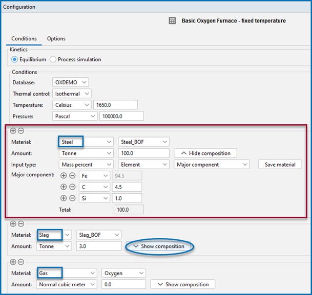
There are three groups to define: Steel (or another user-defined Metal group), Slag, and Gas.
In the image below, the red-highlighted area is where the Steel material group is defined. The drop-down menu that displays Steel_BOF is a user-defined material. This can be defined and then saved to the material library.
The three material group areas on the Process Metallurgy Calculator where you can define components and save materials.
When you click Show composition next to any material group, additional fields display (e.g. Input type, Major components, and so forth) where you can further define each material group. You can add and remove materials using the Material Manager (available via the Configuration window → Options tab).
You can open the example project PMET_01: Basic Oxygen Furnace (BOF) from Thermo‑Calc (Help → Example Files → Process Metallurgy → PMET_01_Basic_Oxygen_Furnace.tcu). Then click Show composition next to the Slag and Gas groups to see how the Slag_BOF and Oxygen materials are defined.
From this composition area you can click the Save material button to add the new material to the group's list. The newly named material composition is then available for use with that material group. In this example, the Steel_BOF material was defined first and then named at the end. It is now automatically available wherever you select the Steel material or need to choose quantities to plot.
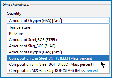
The Amount of X in Y quantities you can choose from the various drop-down lists (such as under Grid Definitions) are defined as Min-Max variation of the component X in Y. If a dependent element is present that is adapted as usual.
To add one or more material groups click the add  button. Click the minus
  button to remove a material group. The new material inherits the default settings of that group.
Click to select a Calculation Type.
- Single: To calculate a single point. The results from this calculation can be displayed in the Visualizations window using a Table Renderer.
- One Axis: To vary a quantity on the X-axis.
- Grid: Evaluates two axis variables of the selected quantities in the specified range and number of steps.
- Uncertainty: Evaluates calculations where the values of the quantities are sampled from Gaussian distributions. The Mean field is as defined under Condition Definitions for the respective quantity. The result is visualized as a histogram or normal probability plot by adding a Plot Render activity.
The Quantity menu displays all the stepping options set up with the material groups for Steel (or any user-defined metal group), Slag, and Gas.
For One Axis, select a Quantity to vary along the X-axis, for example, Temperature then enter a Min, Max, and Number of steps.
For the Grid calculation type, define the two axes variables using the fields and menus: Quantity, Min, Max, and Number of steps. The number of steps along with the minimum and maximum values for the axes define a grid. For each grid point the selected equilibrium is evaluated.
Depending on the calculation type selected, there are also a variety of Plot Types to choose from.
For the Uncertainty calculation type, click to select the applicable checkboxes under Quantity. The Mean field is for the distribution function as defined under Condition Definitions for the respective quantity. The default ΔMin/Max is a 95% confidence interval.
For the Uncertainty calculation type, choose a number of Standard deviations where you want to Truncate the distribution. Choose the Total number of samples.


