Isothermal Solidification During Brazing: A Diffusion Simulation
These examples using the TCS Ni-based Superalloys Database (TCNI) and TCS Ni-alloys Mobility Database (MOBNI) include the use of the recently added element, phosphorus (P).
For other examples using P, see Prediction of Phase Stability with Minor Amounts of P in Ni‑base Superalloys and Predicting Phase Stability: Applications Involving P.
Phosphorus is a common melt suppressant. It is sometimes preferred over boron in filler materials for transient liquid phase joining, also known as brazing, because the substitutional phosphorus has much lower solubility and mobility through the parent metal, thus it is harder for P to penetrate and supersaturate the parent metal and subsequently form embrittling precipitates out of the supersaturation.
The following example plots show the results from the Add-on Diffusion Module (DICTRA) simulation of Ni joined with a Ni-11P filler material, also known by the commercial name BNi-6. The Diffusion Module (DICTRA) requires an additional license although all users can use a demonstration version with up to three components.
Read more about the Diffusion Module (DICTRA) on our website. There is also a Getting Started with the Diffusion Module (DICTRA) page available. If you are in Thermo‑Calc, press F1 to search the help to learn about the available settings included with the Add-on Module.
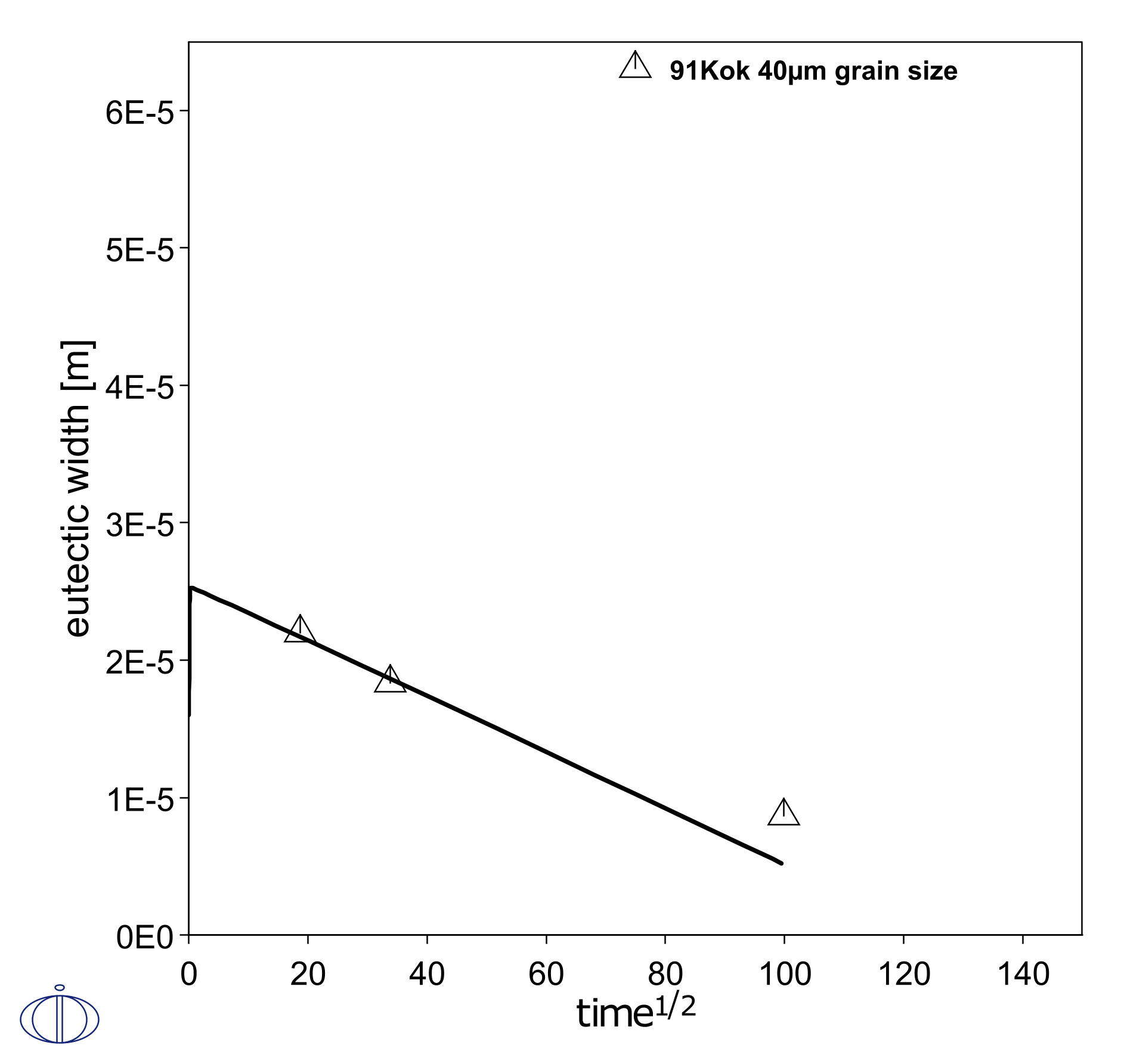
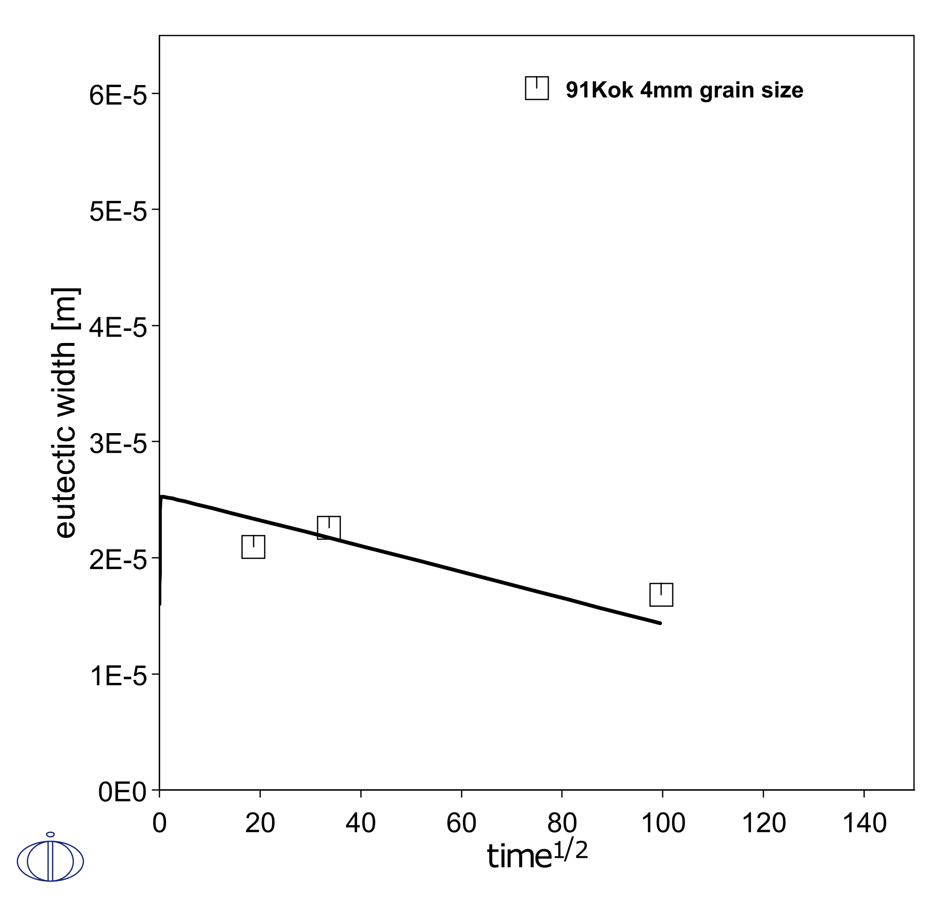
A simple setup is made of half of the experimental geometry, with one region representing half of the filler and one region representing one piece of parent Ni metal. This simulates the isothermal solidification during brazing at 1200 °C for 2.75 hours. Initially, mass balance promotes a rapid growth of the liquid filler region in the first timestep, and the region then shrinks as it solidifies at a rate proportional to the square root of the holding time. This liquid region size is known by measuring the eutectic width after cooling of the joint. Here the grain boundary diffusion model is used to emulate the enhanced penetration into the parent metal due to grain boundaries, as a function of grain size. In Figure 1 and Figure 2 it is shown that a smaller grain size, i.e. more grain boundaries, makes the liquid region shrink faster.
Grain boundary modeling is only available in Console Mode where you use the GB_MODEL command.
Figure 1: Simulated shrinkage of liquid brazing joint during isothermal solidification, with a parent FCC grain size of 40 µm [1991Kok].
Figure 2: Simulated shrinkage of liquid brazing joint during isothermal solidification, with a parent FCC grain size of 4 mm [1991Kok].
Reference
[1991Kok] H. Kokawa, C. H. Lee, T. H. North, Effect of grain boundaries on isothermal solidification during transient liquid phase brazing. Metall. Trans. A. 22, 1627–1631 (1991).

