D_02: Ferrite(bcc)/Austenite(fcc) Transformation in a Binary Fe-C Alloy
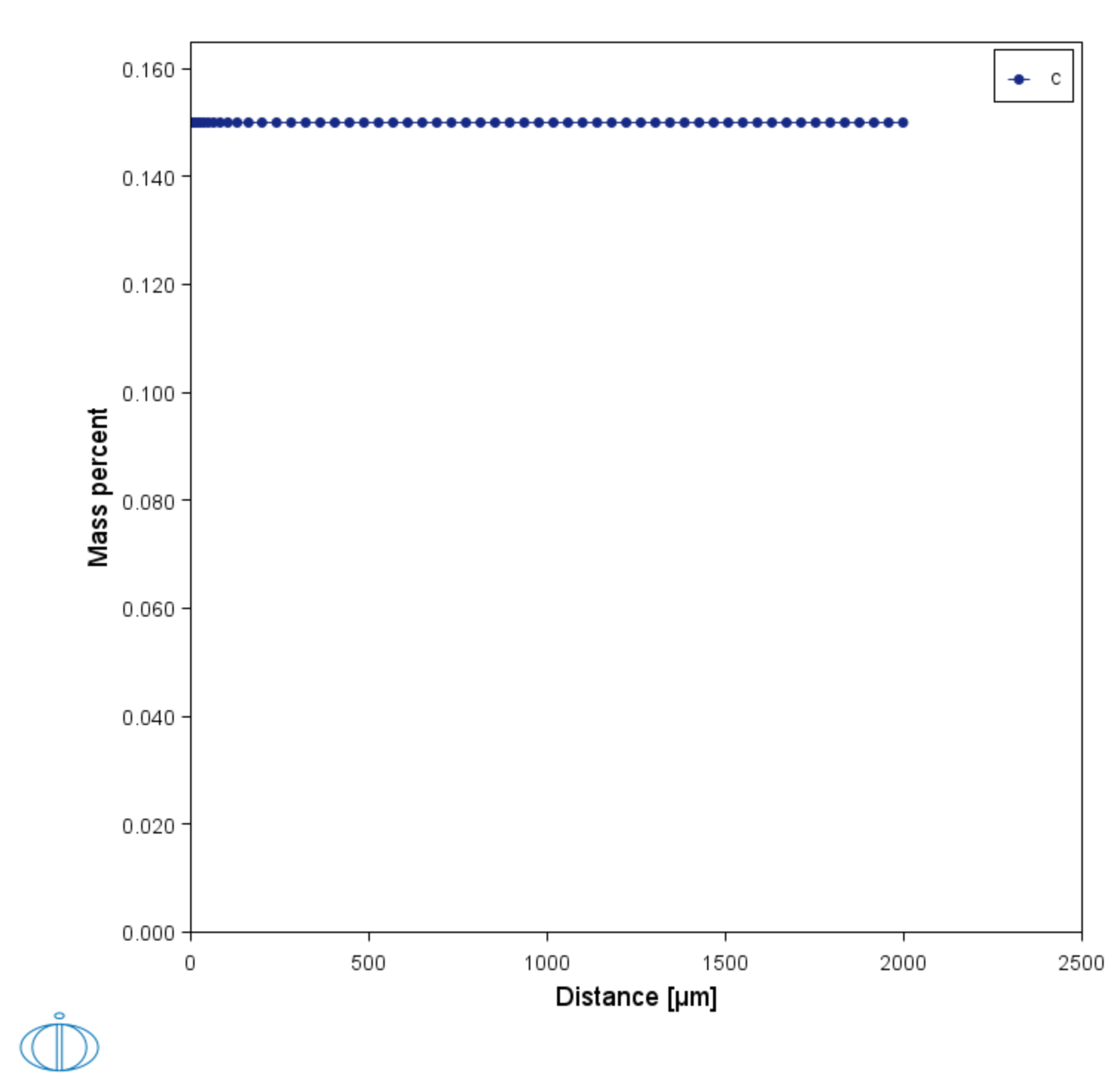
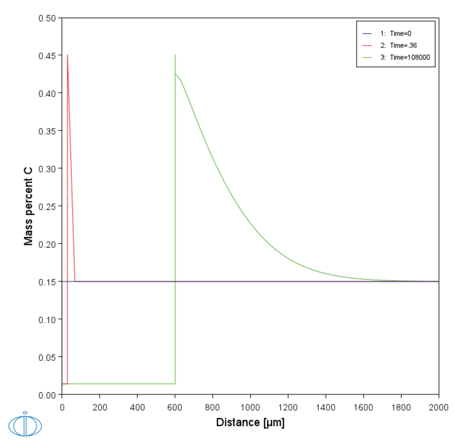
The moving phase boundary example simulates the growth of ferrite (bcc) into austenite (fcc). The austenite is assumed to be initially homogeneous with the composition Fe-0.15 mass-% C. The transformation temperature is 1050 K. The initial thickness of the austenite is 2 mm and an initially very thin ferrite (1 nm) is also present at the start of the simulation.
- Folder: Diffusion Module - DICTRA
- File name:
D_02_Diffusion_Moving_Boundary.tcu
This example is part of the Diffusion Module (DICTRA) Quick Start Guide available to all users. A version of the example is also available for Console Mode.
Visualizations
This example is included as a Diffusion Module (DICTRA) tutorial on our website and as part of the playlist on our YouTube channel.
Open the example project file to review the node setup on the Project window and the associated settings on the Configuration window for each node. For some types of projects, you can also adjust settings on the Plot Renderer Configuration window to preview results before performing the simulation. Click Perform Tree to generate plots and tables to see the results on the Visualizations window.
There is a variety of information shown in the Visualizations window that can be viewed during configuration and after performing the calculation.
- Composition Profiles and Thermal Profile: When setting up a calculator on a Configuration window you can preview the profile and adjust settings as needed. When you click a calculator node in the Project window, the matching name of the node is on the tab(s) displayed in the Visualizations window.
- Plot or Table results: After completing the set up and performing the calculation, to view the matching name of the node on tab(s) in the Visualizations window, either click a Plot Renderer or Table Renderer node in the Project window or click the tabs individually in the Visualizations window.
Figure 1: During set up of the calculation, you can preview the Composition Profile (shown) or Thermal Profile. Click the tab(s) in the Visualizations window to switch between these previews and adjust settings on the Diffusion Calculator Configuration window. For an Isothermal Thermal Profile this shows the constant temperature as entered.
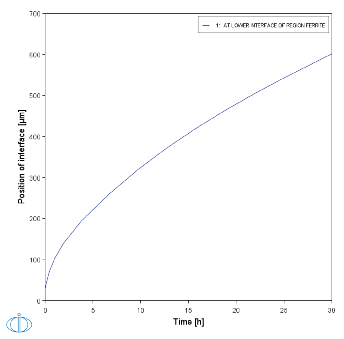
Figure 2: After performing the calculation, you can view the result on the Position of interface vs time tab. In this example, the Plot Renderer is renamed and this matches the tab name in the Visualizations window.


