AM_12: Using AM Calculator Probe Data with the Precipitation Module (TC-PRISMA)
This example demonstrates the coupling of the AM Calculator with the Precipitation Calculator via probe data from an AM simulation. Both a thermodynamic and mobility database is needed for the precipitation calculation, so the AM Material Library cannot be used. Instead, a Scheil Calculator is used to calculate the material properties used in the AM simulation.
The example simulates the incipient melting and re-precipitation of gamma prime in CMSX-4 during Selective Electron Beam Melting (SEBM) during a single pass of the beam. The SEBM process is simulated using a Gaussian heat source. A transient simulation of a single track is simulated, with a cooling time of 150 s. The bed and ambient temperature is elevated to 950 °C. The process parameters are taken from Ramsperger et al. [2016aRam].
- Folder: Additive Manufacturing
- File name: AM_12_AM_Probe_to_Precipitation.tcu
A separate license is required to perform calculations with the Additive Manufacturing (AM) Module. This example also requires a license for the Precipitation Module (TC-PRISMA), plus additional database licenses for the TCS Ni-based Superalloys Database (TCNI) (TCNI12 and newer), and the TCS Ni-alloys Mobility Database (MOBNI) (MOBNI6 and newer).
Background
Ramsperger and Körner [2016bRam] demonstrated that it is possible to print single crystal CMSX‑4 components using SLBM with an elevated bed temperature. The main challenge encountered is fracture during printing. The formation of gamma prime may incur a drop in ductility that contributes to fracture. Understanding the precipitation kinetics of gamma prime during 3D printing is important with regards to identifying optimum process parameters, and determining how best to heat treat the final component.
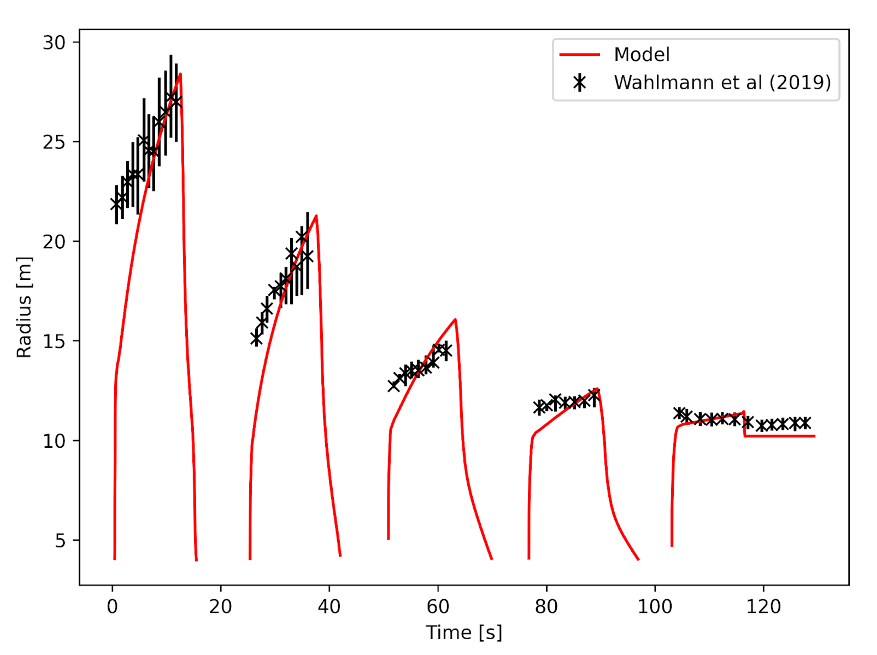
Wahlmann et al. [2019Wah] studied gamma prime kinetics in emulated SLBM thermal conditions, indirectly measuring the size of the gamma prime using X-ray diffraction during repeated nucleation and dissolution thermal cycles imitating the thermal history of an SLBM build. Figure 1 shows the calibration of the Precipitation Calculator to capture the measured kinetics.
Figure 1: A comparison of the indirectly measured gamma prime size evolution during thermal heat treatment emulated an SLBM process with predictions from the Precipitation Calculator using the Thermo-Calc Ni-based superalloys databases (TCNI12 and MOBNI6) [2019Wah].
This AM Calculator to Precipitation Calculator example uses the calibrated parameters for gamma prime kinetics shown in Figure 1. The Precipitation Calculator includes the possibility for incipient melting of the gamma prime, which is predicted to occur during the first pass of the electron beam. Incipient melting describes the phenomena where solid-state precipitates are heated rapidly to a high temperature beyond their solvus temperature. The precipitates reach a temperature where they melt before the parent matrix phase. The Precipitation Calculator removes the gamma prime dispersion upon melting.
Configuration and Calculation Set Up
The Additive Manufacturing template was used to first add the System Definer, Scheil Calculator, AM Calculator, and Plot Renderer to the Project window tree. Additionally, a Precipitation Calculator was added as a successor to the AM Calculator in order to automatically import the time-temperature profile from the AM simulation into the precipitation simulation.
Open the example to see the Project tree layout and review the settings for each activity. It is useful to click around in the interface to understand where the settings are located and configured. This section highlights the relevant settings for this example.
System Definer
On the System Definer, the nickel-based superalloy CSMX-4 composition was approximated by Ni-9.8Co-6.4Ta-6.5Cr-6.4W-5.7Al-2.8Re-0.97Ti-0.62Mo-0.086Hf, (mass%). The thermodynamic (TCNI) and mobility (MOBNI) nickel-based superalloy databases were selected, with the phase DIS_FCC_A1 included.
You can include or exclude phases from the Phases and Phase Constitution tab on the System Definer.
AM Calculator
On the AM Calculator Configuration window, the calculation type Transient is selected with a single track scan pattern and Geometry of 5 mm x 5 mm x 5 mm (height x width x length). The Base plate temperature and Ambient temperature is set to 950 ℃.
Additional settings are then made on the Configuration window as follows.
- In the Heat Source section, Gaussian is selected with a Power of
180W, and a User-defined Absorptivity of85%. - In the Scanning Strategy section, the Scanning speed is
300mm/s and the Layer thickness is50μm. A Cooling time of150s is included. - In the Top Boundary Conditions section, the Evaporation checkbox is selected to include this in the model.
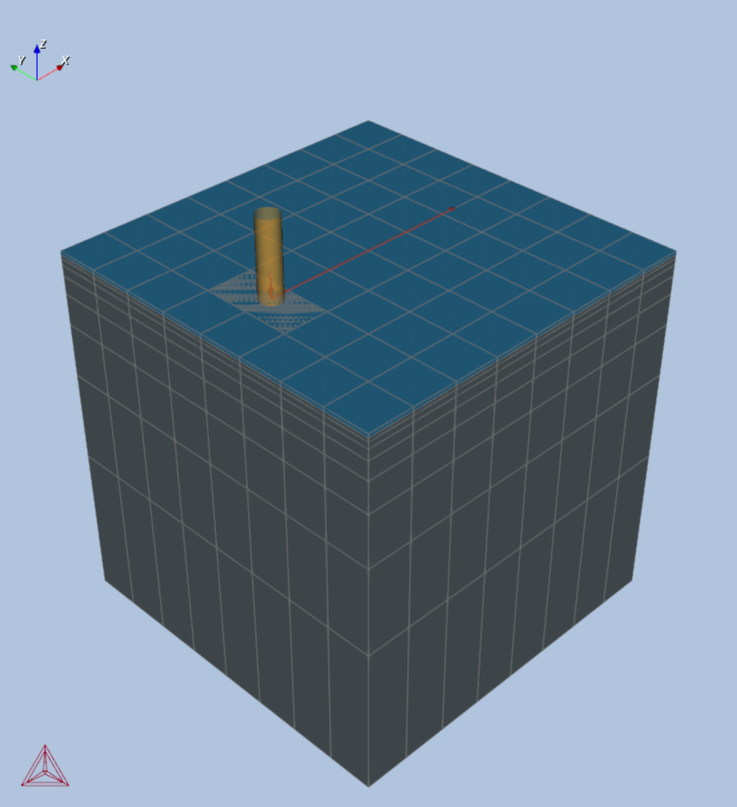
- In the Probe Positions section, a single probe is added to the center of the top surface of the component, below the powder layer. See the Geometry tab as shown in Figure 2.
Figure 2: The full geometry set up for the single track AM simulation with a probe point added to the middle of the scan. Open the example to better see the set up and try working in the Visualizations window.
Precipitation Calculator
The following highlights the relevant settings to make on the Configuration window for this example.
On the Options tab:
- Both the Preprocess equilibrium data and Include incipient melting checkboxes are selected.
On the Conditions tab, under Matrix Phase:
- DIS_FCC_A1 is selected.
- Click Show Details, then for Mobility adjustment > Prefactor, keep Same for all elements and enter
6.0for the Prefactor.
On the Conditions tab, under Precipitate Phase:
- FCC_L12#2 is selected.
- Nucleation sites = Bulk
- Interfacial energy =
0.035J/m2 - Click Show Details, then:
- Phase energy addition =
-55.0J/mol
- Select the Preexisting size distribution checkbox.
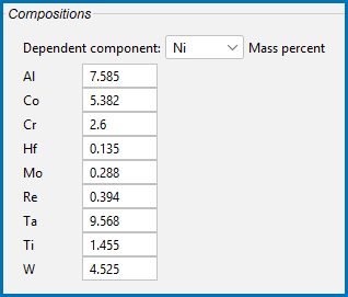
- Click Edit Particle Size Distribution, and note the Compositions entered.
- Phase energy addition =
In the Preexisting Particle Size Distribution window you can also adjust other settings.
On the Conditions tab, under Calculation Type:
- Temperature unit = Kelvin
- Start time =
0.0 - Simulation time =
150.01Seconds - Probes: Probe1
- Condense time-temperature data = None
Visualizations
Many of our Graphical Mode examples have video tutorials, which you can access in a variety of ways. When in Thermo‑Calc, from the menu select Help → Video Tutorials, or from the main My Project window, click Video Tutorials. Alternately, you can go to the website or our YouTube channel.
Open the example project file to review the node setup on the Project window and the associated settings on the Configuration window for each node. For some types of projects, you can also adjust settings on the Plot Renderer Configuration window to preview results before performing the simulation. Click Perform Tree to generate plots and tables to see the results on the Visualizations window.
There is a variety of information shown in the Visualizations window that can be viewed during configuration and after performing the calculation(s).
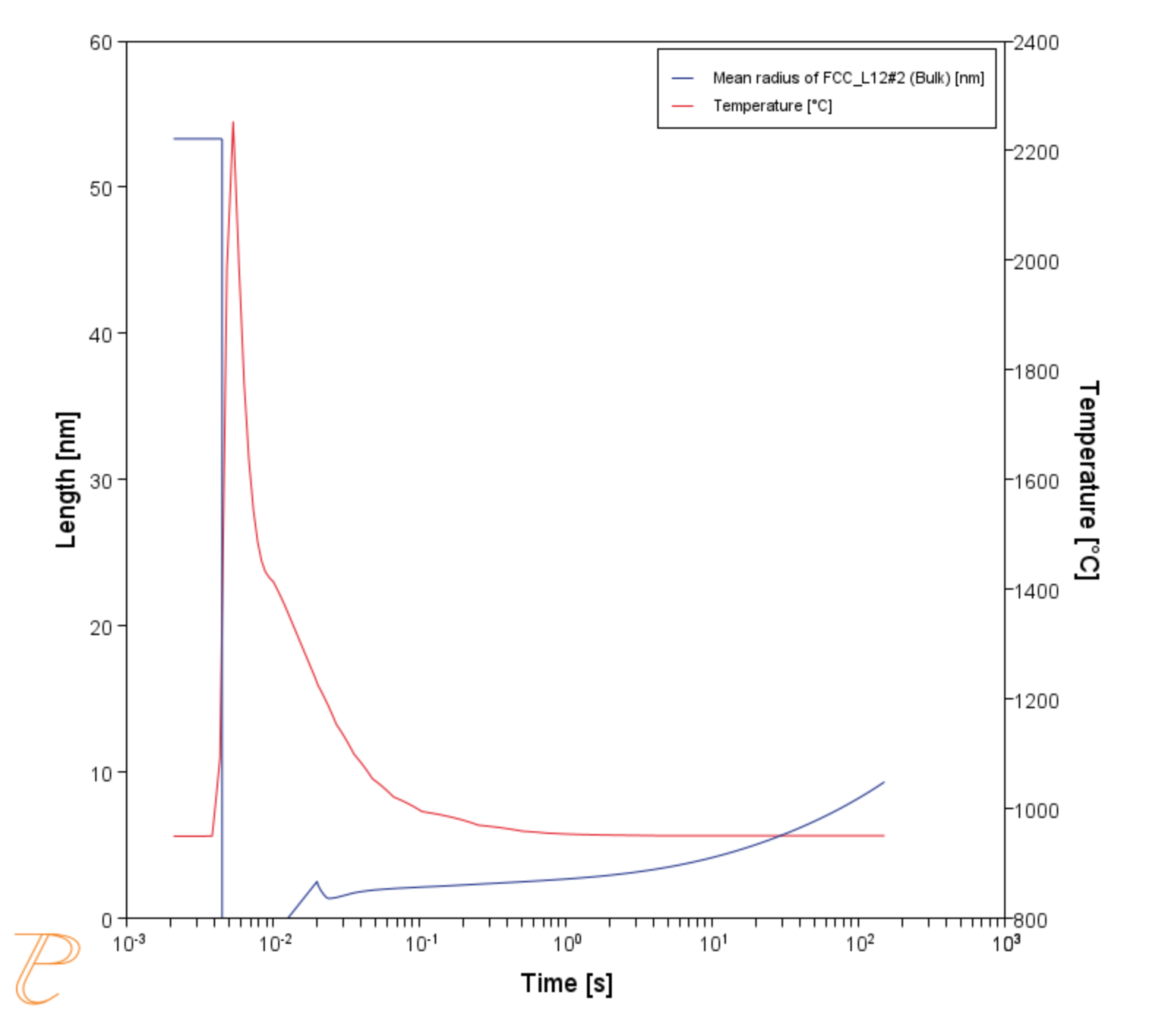
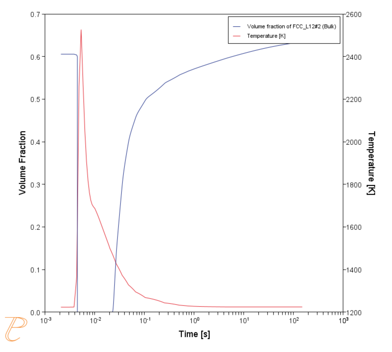
Figure 3 and Figure 4 show the predicted evolution of the precipitate dispersion including the change in mean radius and volume fraction, respectively. The second Y axis in both figures shows the temperature. The initial gamma prime size distribution describes the gamma prime that has formed during the production of the AM powder. It is too large to dissolve during the rapid heating as the electron beam heats the component, and melts before the matrix. The gamma prime re-precipitates upon resolidification and cooling below the gamma prime solvus, and coarsens whilst held at elevated temperature. The incipient melting of the initial size distribution is clearly evident.
Figure 3: The mean radius and temperature as a function of temperature, with the mean radius on the left axis, and the temperature on the right axis.
Figure 4: The volume fraction and temperature as a function of temperature, with the volume fraction on the left axis, and the temperature on the right axis.
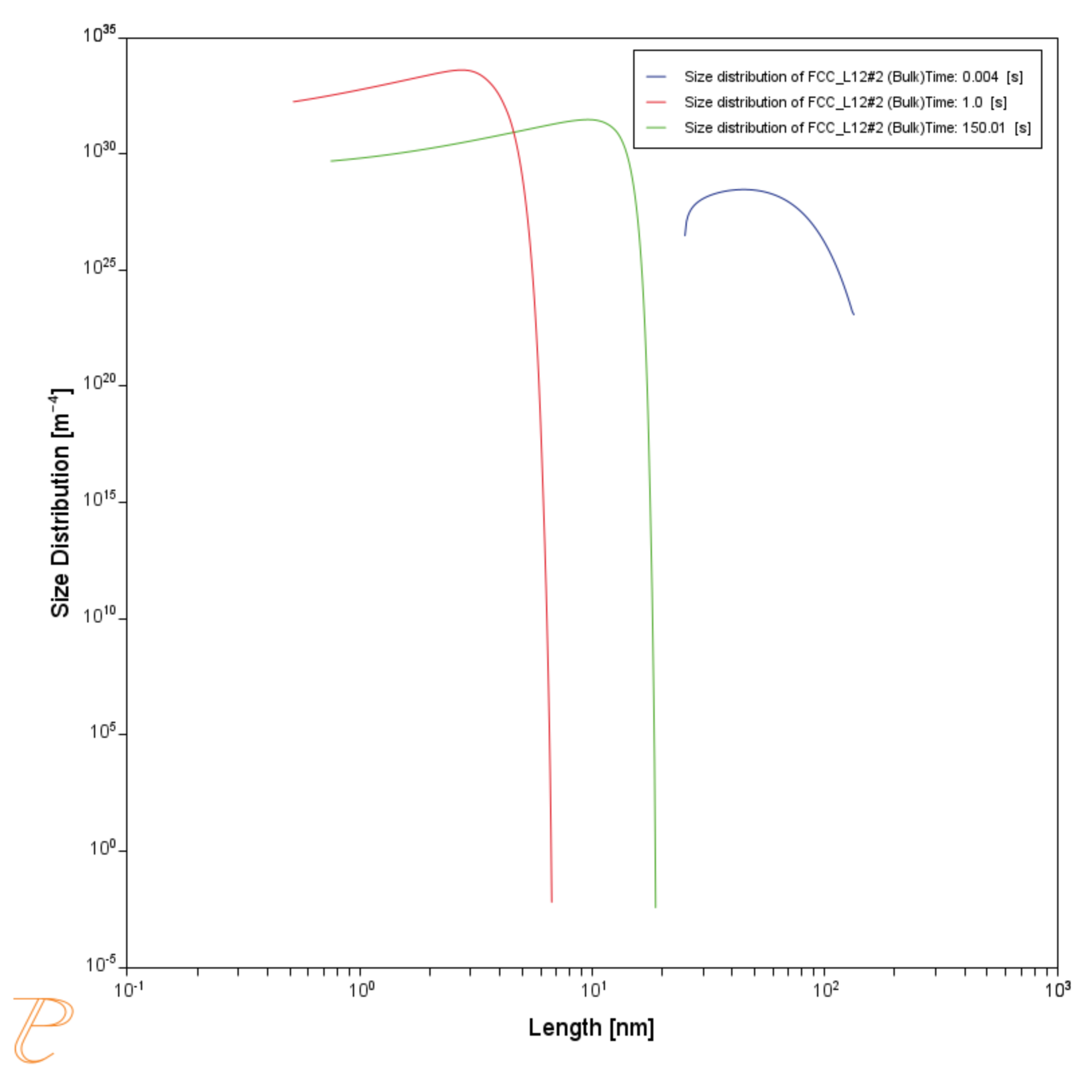
The gamma prime distribution just prior to incipient melting is observed at 0.004 s. It has not dissolved significantly during the rapid heating as the electron beam passes. At 1 s the material has solidified and cooled to a temperature where gamma prime has nucleated and grown. The size distribution at the end of the simulation is shown at 150.1 s. Figure 5 shows the size distributions at these times during the single track AM simulation.
References
[2016aRam] M. Ramsperger, R. F. Singer, C. Körner, Microstructure of the Nickel-Base Superalloy CMSX-4 Fabricated by Selective Electron Beam Melting. Metall. Mater. Trans. A 47, 1469–1480 (2016).
[2016bRam] M. Ramsperger, C. Körner, “Selective Electron Beam Melting of the Single Crystalline Nickel-Base Superalloy CMSX-4®: From Columnar Grains to a Single Crystal” in Superalloys 2016 (John Wiley & Sons, Inc., Hoboken, NJ, USA, 2016), pp. 341–349.
[2019Wah] B. Wahlmann, F. Galgon, A. Stark, S. Gayer, N. Schell, P. Staron, C. Körner, Growth and coarsening kinetics of gamma prime precipitates in CMSX-4 under simulated additive manufacturing conditions. Acta Mater. 180, 84–96 (2019).
Other Resources
Read more about the Additive Manufacturing (AM) Module on our website including the details about database compatibility or to watch an introductory webinar. You can also use the Getting Started Guide to learn about the key features available.
